Overview
The purpose of this design is to efficiently design a voting process so that we can get the output faster and digitally stronger. As long as the circuit works efficiently and correctly we have a working voting process. We can only use gates that have two inputs and have to use the materials provided to us. In case of a tie the President is the tie breaker. If the president is included the vote is good if not then the vote does not.
Problem Conception
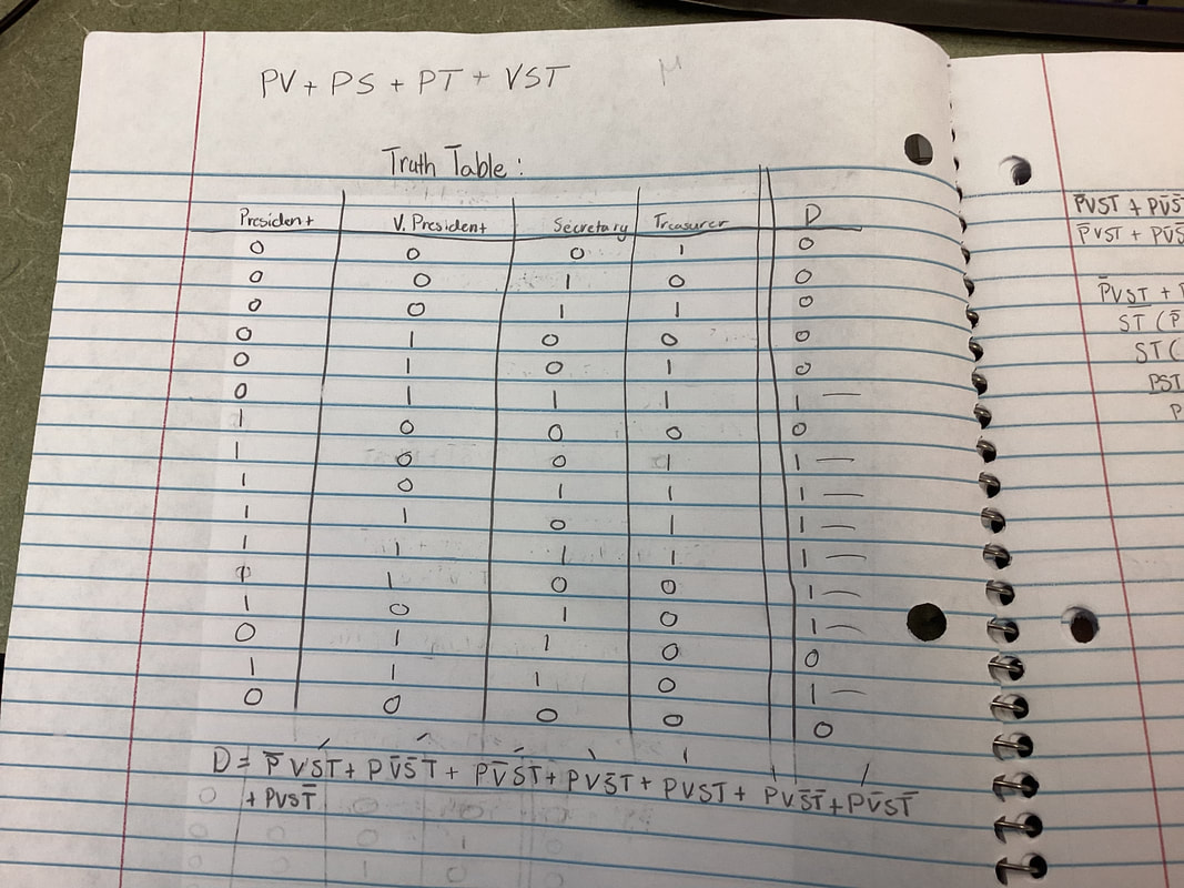
The purpose of a truth table is so that we can get the un-simplified expression back. The variables show what they are representing the people voting: President, Vice President, Secretary, and Treasurer. The numbers show if they voted yes or no. by showing 1's and 0's. The truth table shows the tie breaker by the president over ruling. So if the president votes yes with any other person and the other two say no. then it is a yes for the vote. If the president is not apart of the vote then it does not go through.
The un-simplified is seen in the picture above, showing the votes for yes in an expression to what we get the yes vote from. This expression is in SOP form. I got this expressions from the description given to me in the project. if three or more are yes then the vote is yes, but if its a tie the president breaks the tie. I chose SOP form because it is easier to use when going to a simplified version of the expression.
Un-Simplified Circuit
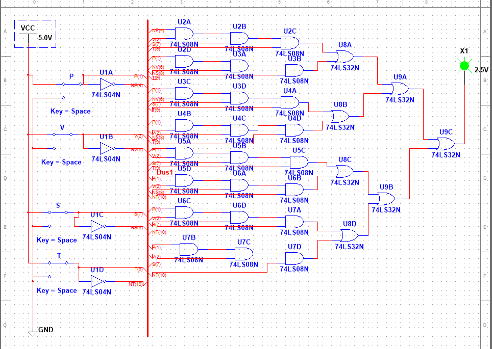
I first made the switches so that they connected to power and ground. Then I put not gates for each variable to connect to. so then I could connect it to the bus so that I can organize the circuit to be able to read it. Then I created 8 lines of gates with three gates in each line, and then i connect them all with OR gates so that they can create the output needed. We need to use 4 NOT gates, 24 AND gates, and 7 OR gates. To create this in breadboard form you would need 6 AND gate chips, 1 NOT gate chip, and 2 OR gate chips.
Boolean Algebra Simplification
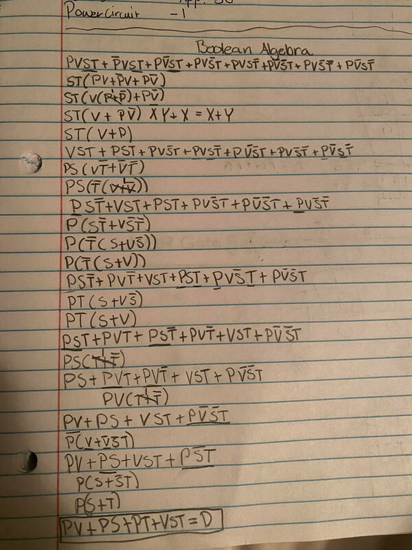
To get the Simplified version of the circuit we need to first go through the steps of Boolean algebra. This step took the longest to figure out because in order to do it right you had to make sure your steps didn't get all tangled together, or for the steps to be right so that you can get the simplified version needed. The simplified expression is: D= PV + PS +PT + VST
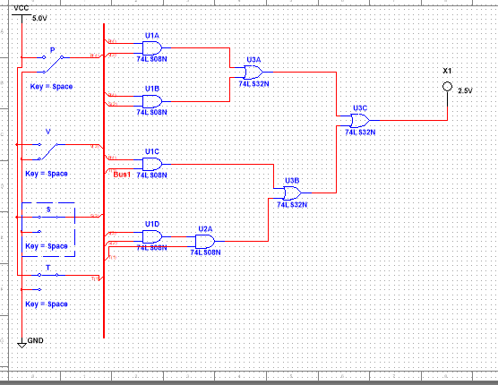
Simplified Circuit
|
I created the simplified circuit with bus form so that is organized in a neat way that is easily read. I started grounding and powering the switches for each variable. Then I connected them to the bus. Then I created four lines with three of them only one gate and one of them having two gates. Then I connected then to OR gates so that I can connected the final expression to the LED. I used a total of 0 NOT gates, 5 AND gates, and 3 OR gates. This means for the gate chips we only need 0 NOT chips, 2 AND chips, and 1 OR chip. I figured this out by seeing how many gates I could have in a chip, and for the AND or OR gates I could only have 4 gates. I needed 2 AND chips to get all the outputs I needed. I was able to figure out the amount by the lovely sheets Mrs. Zienty provided for us. They helped alot when bread boarding.
|
|
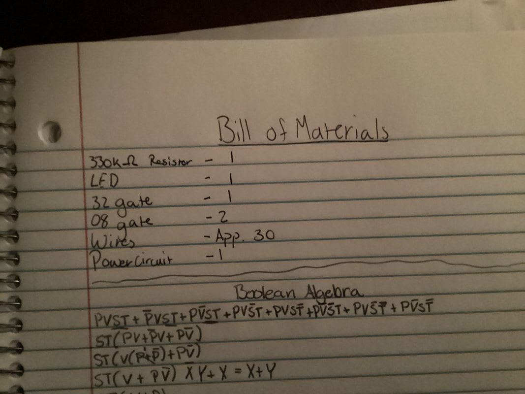
Bill of Materials
In the table we are just keeping track of the amount of materials for each component we will use. This helps keep us organized and keep track of the components. It is also informative for our teacher in case she feels we misplaced some of our materials.
|
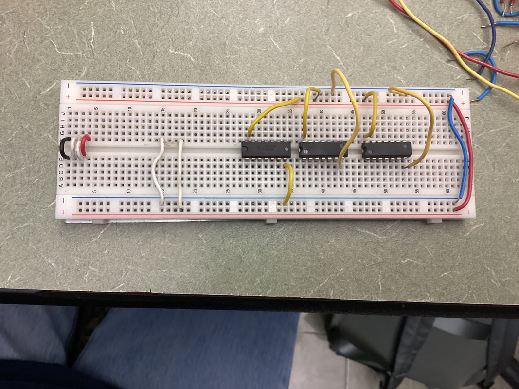
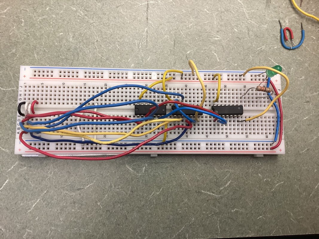
Bread-Boarding CircuitThe First picture shows me putting the basics on the breadboard. I connected my busses. I grounded and powered my gates. I know you can't see the green board, because I let someone borrow it. I connect my power to positive and my 0 volts to negative. Then the small wires in sets of four, our just connecting the switches so that they are better organized.
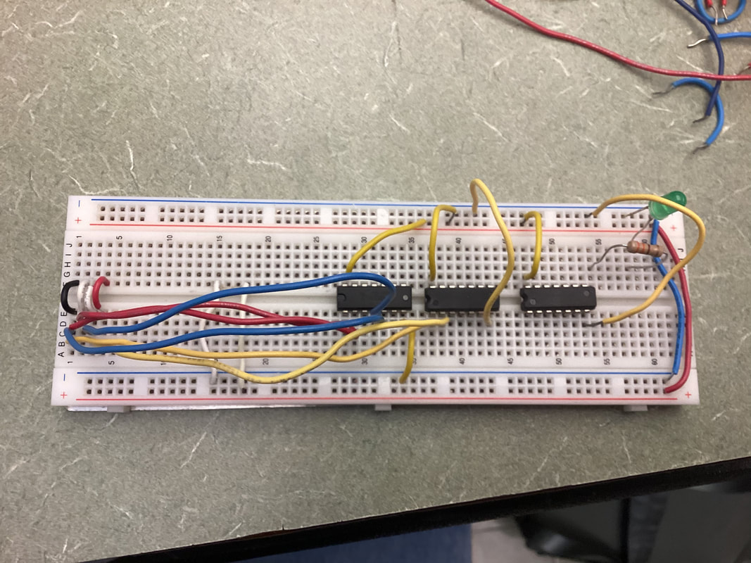
The second photo is me connecting so I can get the outputs: PV, PS, & PT. Then I added my resistor and LED so that I didn't mess them up later on down the road. The third image is me finally finishing with all the AND outputs and connecting them to the OR gates so that I can get the output I want. 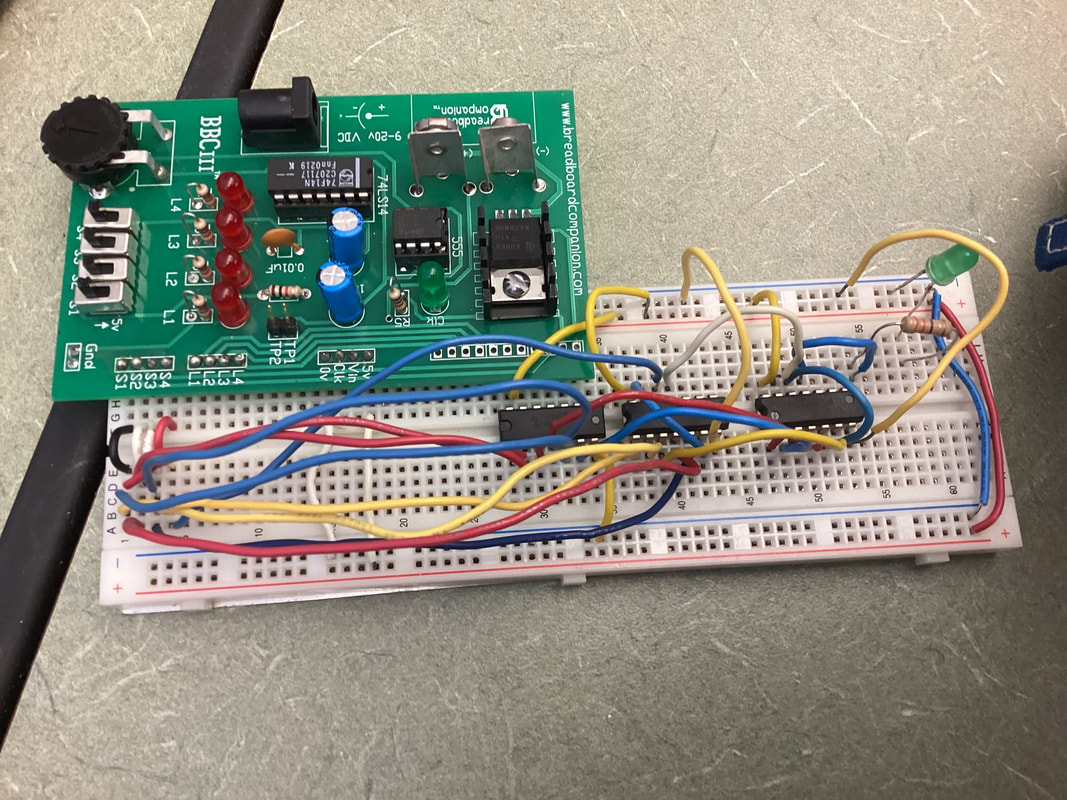
|
My first time bread-boarding in this class I felt like an idiot, because I had all my connections correct but my LED and resistor were wrong. My breadboard was all organized so that I could see what was going wrong with it, but little did I know that me LED and resistor were messed up. I had everything else figured out. This made me learn to makes sure I have my connections right because something simply as a LED can mess you up. Now to make this circuit work, I wasn't as organized. So when I knew I had a problem I went back and color coded it, and realized my connection for the letter T was one by itself. So in order to fix that I went back with the connection and connected it to VST as it was suppose to be and it worked. Organization and routine is key.
Conclusion
I think the most important take away is making sure your boolean algebra is right when you go with each step. It took me eight pages to finally figure out how to do it. Yes I was doing my algebra right, but the expression is so long starting in the right spot will get you to end in the right spot otherwise you will get stuck. This project showed my organization and time management. The best thing this project shows is perseverance, sticking it out even though you have to try try again. I would say the basic process is: statement, truth table, un-simplified expression, boolean algebra, simplified expression, and bread-boarding. Boolean algebra is useful, because if we were to use the un-simplified expression on the breadboard we would have failed. Putting that together with wires and gates would have not only taken for forever but also not efficient. We would have to use triple the materials and time, meaning that triples the amount of money on manufacturing. This is not affordable, time wise, nor is it efficient for the consumers.
